 MultiCrown
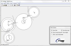
The loaded rollers that press water out of the paper sheet during paper making can be arranged in clusters at various angles, such as the 4-roll press shown to the left. The rolls bend and deform and are “crowned” to obtain shapes that result in even contact pressure from one end of the roll to another. The optimum crown shapes depend on all the loads, weights, suction pressures, felt tensions, and properties and dimensions of the metal roll shells. The MultiCrown program uses a simple CAD-style interface to input the roll dimensions and loads and then outputs a report that can be sent to a grinder to produce the optimum shapes. Behind the scenes is a 3D finite element calculation engine.
For the end users, the first step is to select what kind of cluster, such as two-rolls or the 4-roll press shown above. Then, the user drags the rolls to the correct angles or enters the angles into the text boxes. Then the loads are input. The exact properties and dimensions for each roll may be edited by double-clicking on a roll.
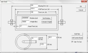
The roll inputs shown on the left are easily obtained by the end user. The weight of the roll can be estimated from the dimensions, and the stiffness of the shell material may be pulled from a database.

Most analyses predict the beam-bending mode, where the roll is modeled like a simple beam. The beam deflection looks similar to that shown on the left. Sadly, for large diameter shells that are thin, the deflection is more complicated, and simple beam equations are not up to the task. Perhaps the easiest way to visualize the roll deformations is to squeeze an aluminum can in the center and see what shape it takes.

For tin cans, notice that the stiff heads on the ends constrain the outer shell to remain circular. Also notice that the top and bottom surfaces do not follow one another. Beam theory generally under-predicts the deformation and sometimes is off by a factor of 10. The undesirable result is that the ends will be loaded far more heavily than the center. This condition can cause poor sheet profiles, increased barring, faster wear rates for the roll coatings and press felts, and sometimes material failure.

We may gain more insight by looking at the cross sectional view at the midpoint along the length of the rolls. Note that the roll on the left bends away like a beam, where the center is pushed away. The roll on the right shows that the center of the roll is not pushed very far, yet the shell deforms like a tin can. We exaggerated the deflections for this picture.
I programmed a 3D finite element solution for this application, since there really is no closed form solution. The end users do not need to worry about the complexity of the math or process. They simply get a report that shows the deformed shape.

The program also models yankee dryers, so we included internal pressure and temperature gradients. On the left we can see how the deformed hot production yellow mesh differs from the base-line cold red mesh in the presence of temperature variations. The entire roll expands, as we expect with the higher service conditions. Also, there is some outward dishing of the heads and some shell bulging at the outer roll surface. Depending on the shapes, it can require a fairly complicated crown shape to produce uniform loading.
In terms of software, this is a Windows application that was written in C++ using MFC and Visual Studio. MultiCrown outputs reports in Excel, 2D mesh cross-sections in DXF, and 3D models in VTK for subsequent rendering.